- CN
- EN

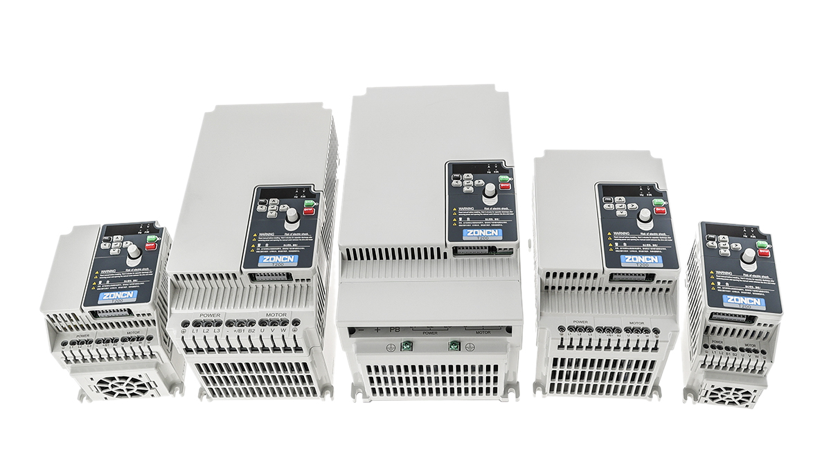
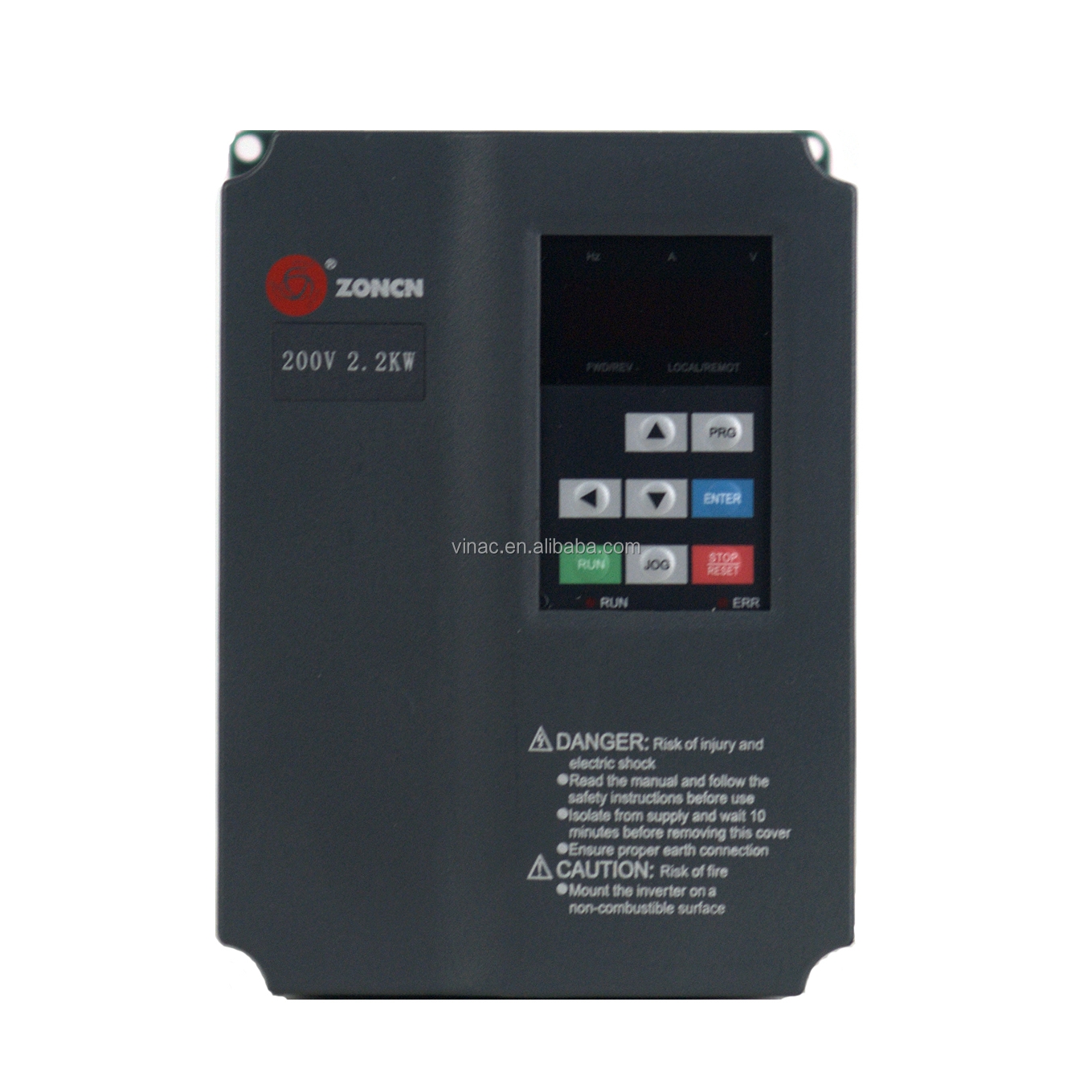
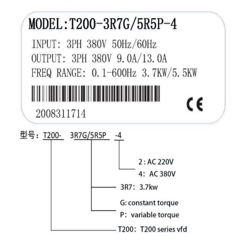
ZONCN
Inverter, Frequency Converter, VFD, Variable Frequency Drive, VSD, Variable Speed Drive, AC Driver, Power Inverter, Static Frequency Converter, Three-phase Inverter, Single-phase Inverter, Variable Voltage Variable Frequency Drive, Industrial Inverter
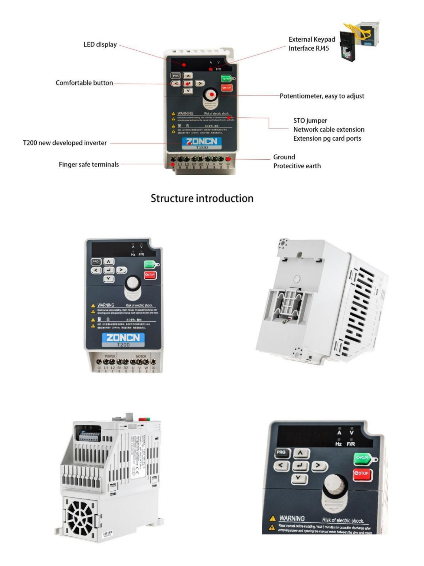
· Economically affordable; Micro compact design
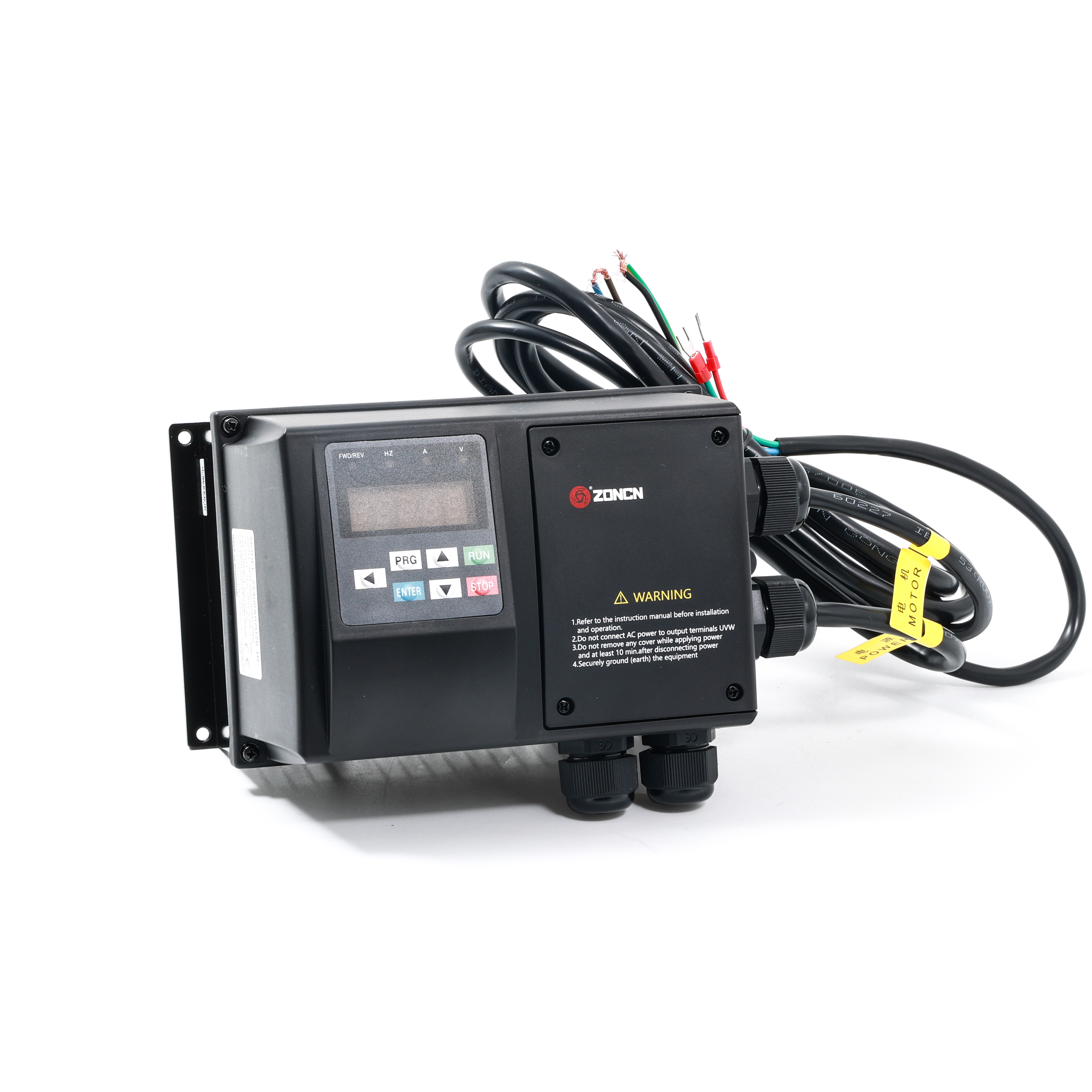
· Easy to use and install: DIN rail installation(below 3.7KW), keyboard cable with RJ45,STO function (support 380V below15kW), built-in EMC filter, 24VDC power supply, PID adjustment.
· V/F control, open-loop vector control, closed-loop vector control mode
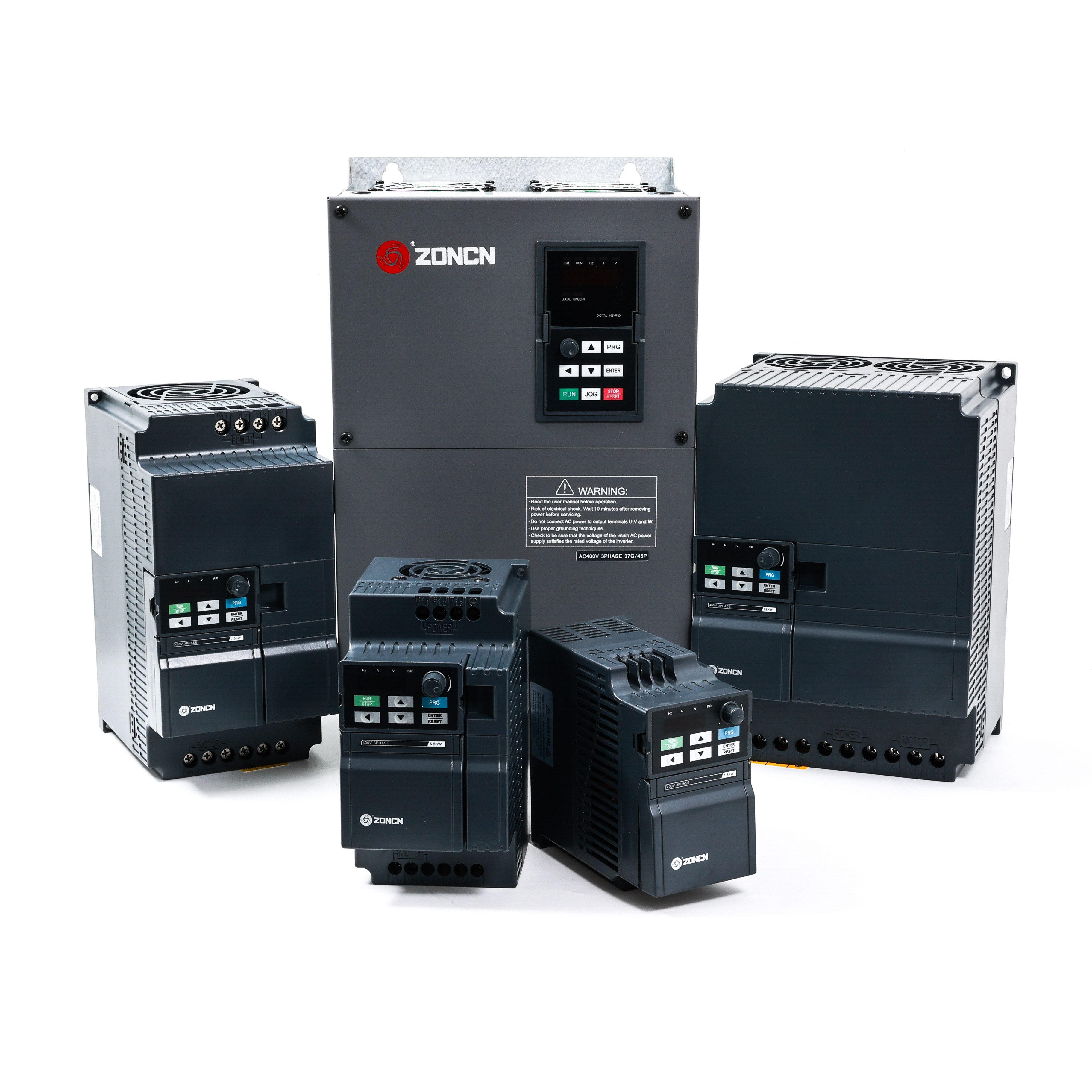
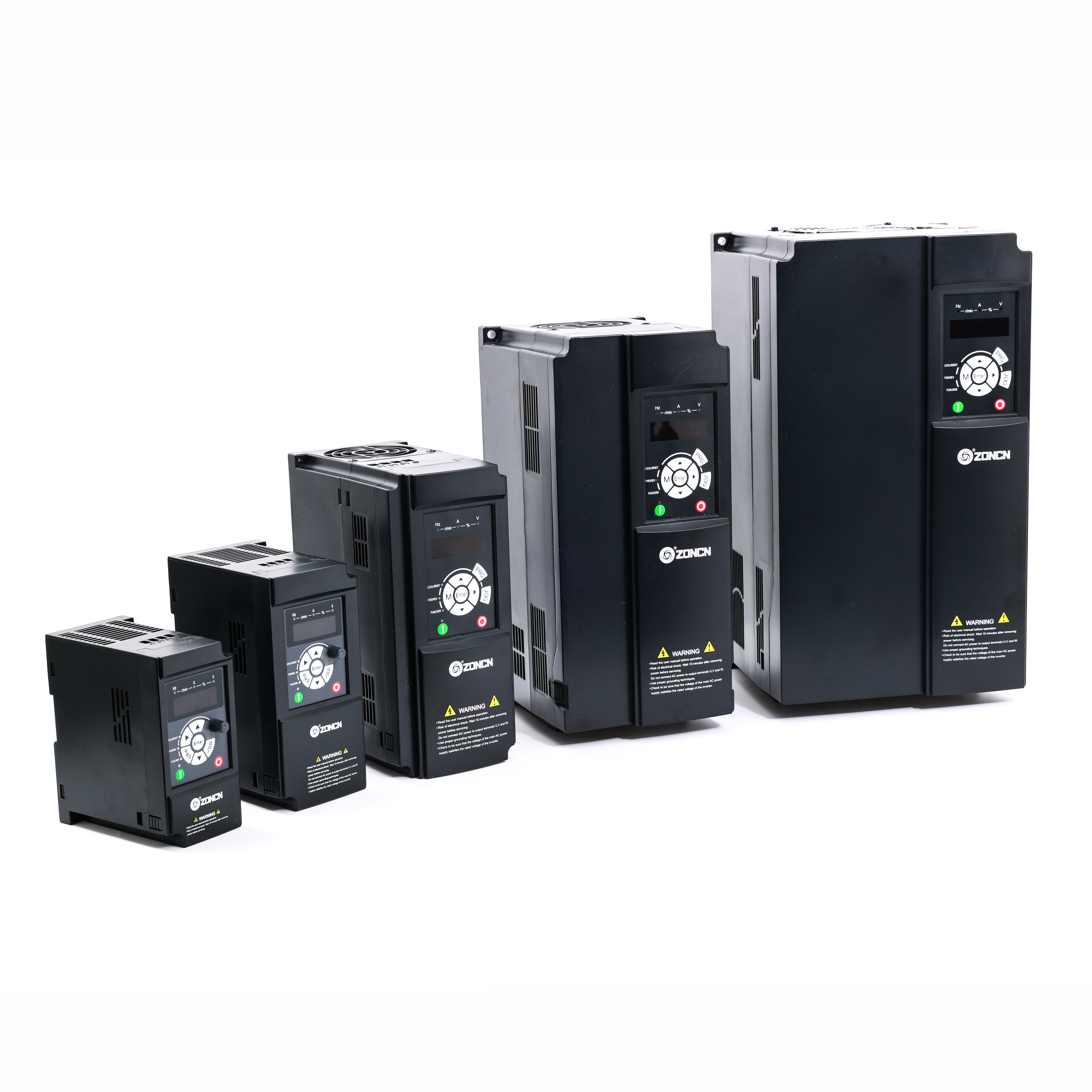
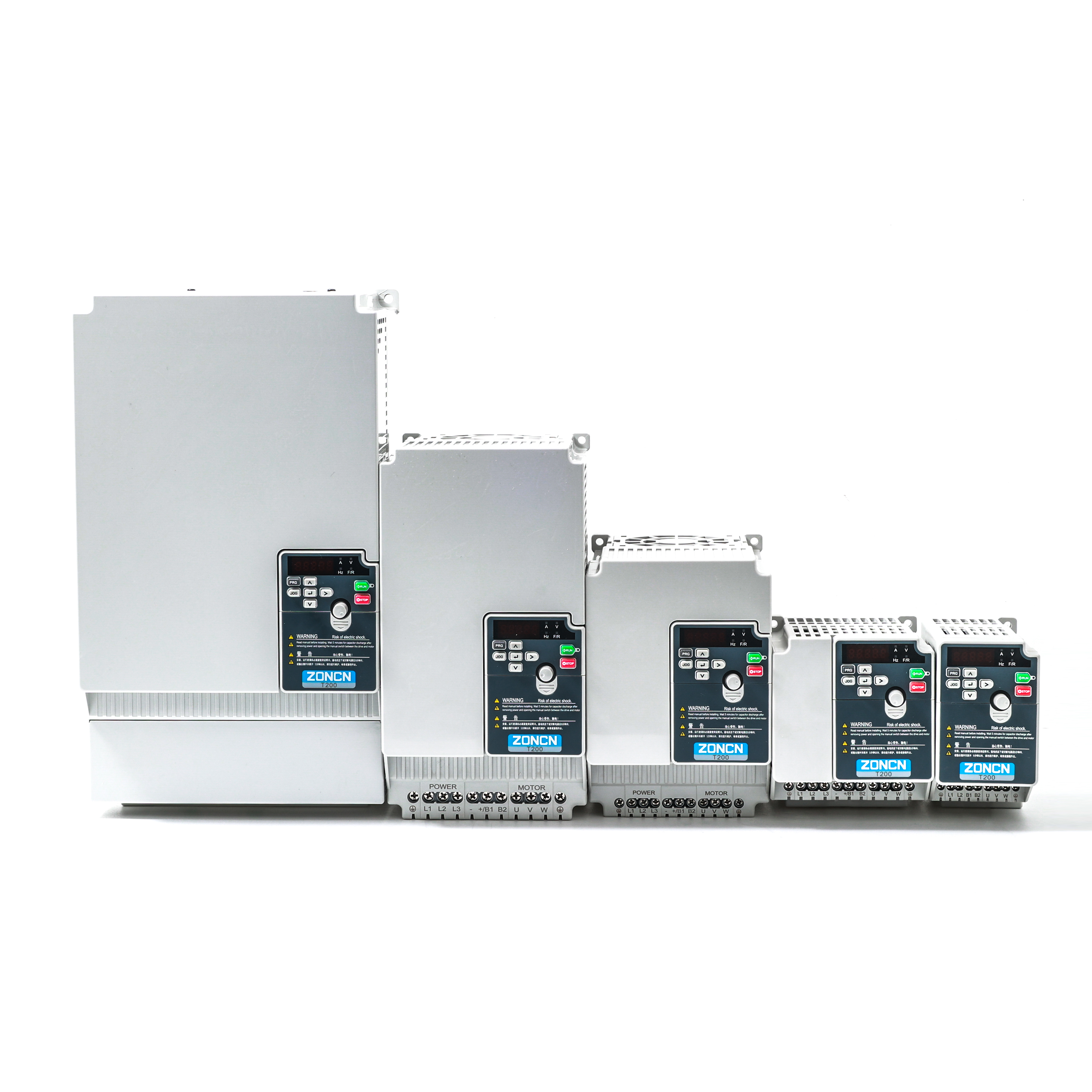
· Power range 220V 0.4~2.2kW 380V 0.4~55kW
· Frequency range 0~599Hz
· Supporting multiple expansion cards: EtherCAT, Profibus-DP, ProfiNet, ModbusTCP, CAN open, Digital I/O, PG card
· External keyboard parameter copying function and automatic parameter back-up.
ITEM | T200 | |
Basic function | Maximum frequency | 0~600.00Hz |
Carrier frequency | 0.5kHz~16kHz | |
The carrier frequency can be automatically adjusted based on the load features. | ||
Input frequency resolution | Digital setting:0.01Hz | |
Analog setting: maximum frequency×0.025% | ||
Control mode | Voltage/Frequency control (V/F) | |
Sensorless flux vector control (No PG) | ||
Closed loop vector control (Have PG) | ||
Startup torque | G Type:0.5Hz/150%(No PG); | |
P Type:0.5Hz/100% | ||
Speed range | 1:100(No PG) | |
Speed stability accuracy | ±0.5%(No PG) | |
Torque control accuracy | ±5%(Have PG) | |
Overload capacity | G type: 60s for 150% of the rated current, 3s for 180% of the rated current. | |
P type: 60s for 120% of the rated current, 3s for 150% of the rated current | ||
Torque boost | Fixed boost | |
Customized boost 0.1%–30.0% | ||
V/F curve | Straight-line V/F curve | |
Multi-point V/F curve | ||
N-power V/F curve (1.2-power, 1.4-power, 1.6-power,1.8-power, square) | ||
V/F separation | Two types: complete separation; half separation | |
Ramp mode | Straight-line ramp | |
S-curve ramp | ||
Four groups of acceleration/deceleration time with the range of 0.0–6500.0s | ||
DC braking | DC braking frequency: 0.00 Hz to maximum frequency | |
Braking time: 0.0-100.0s | ||
Braking action current value: 0.0%–100.0% | ||
JOG control | Jog frequency range:0.00Hz~50.00Hz. JOG acceleration/deceleration time0.0s~6500.0s。 | |
Onboard Multiple preset speeds | It implements up to 16 speeds via the simple PLC function or by input terminal states | |
Onboard PID | It realizes process-controlled closed loop control system easily. | |
Auto voltage | It can keep constant output voltage automatically when the mains voltage changes. | |
regulation (AVR) | ||
Over-voltage/ | The current and voltage are limited automatically during the running process so as to avoid frequent tripping due to over-voltage/over-current. | |
Over-current stall | ||
control | ||
Rapid current limit | It helps to avoid frequent over-current faults of the inverter. | |
Torque limit and torque control | It can limit the torque automatically and prevent frequent over-current tripping during the running process. | |
Individualized function | High performance | Control of asynchronous motor is implemented through the high-performance current vector control technology. |
Instantaneous stop doesn’t stop | The load feedback energy compensates the voltage reduction so that the AC drive can continue to run for a short time. | |
Timing control | Timing range 0.0Min~6500.0Min | |
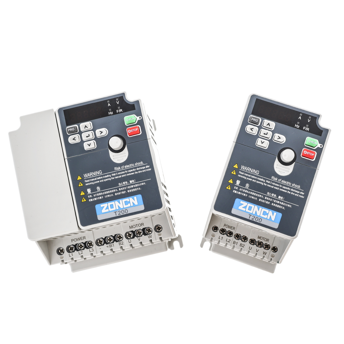
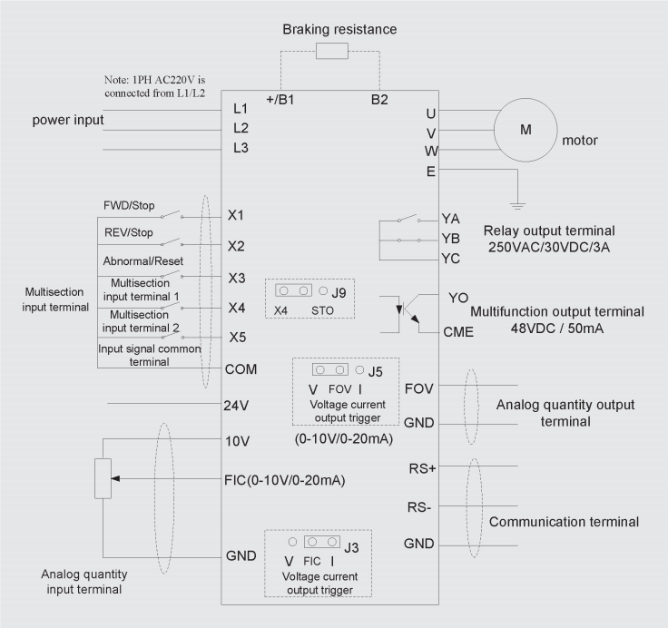
Communication methods | RS-485 | |
Operation | Running command channel | Given by the panel, control terminals, serial communication port, can be switched by many ways |
Frequency source | 10 kinds of frequency source, given by digital analog voltage, analog current, Pulse, serial port. can be switched by many ways | |
Auxiliary frequency source | There are ten auxiliary frequency sources. It can implement fine tuning of auxiliary frequency and frequency synthesis | |
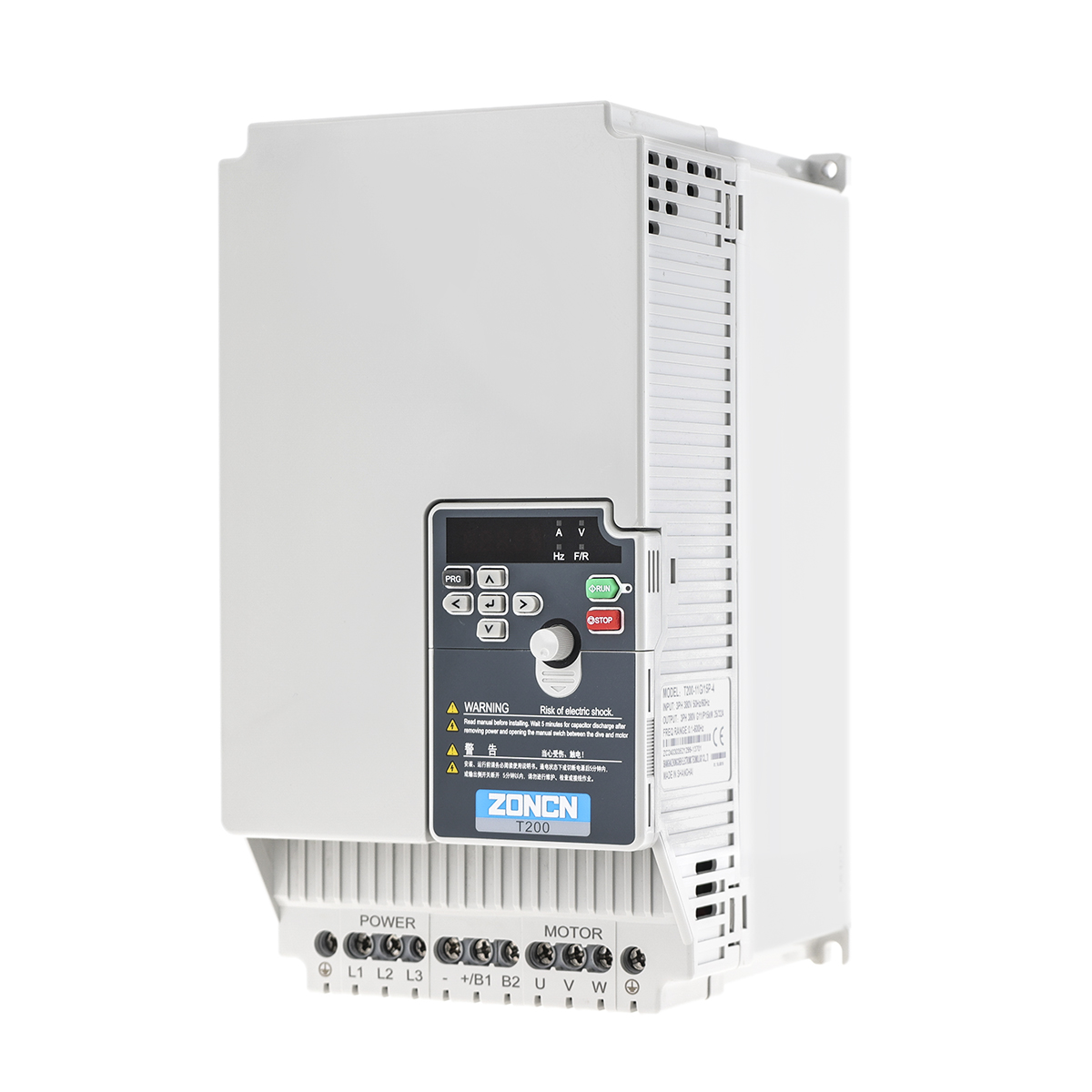
Input terminals | 5 digital input terminals, one of which supports up to 100 kHz high-speed pulse input; | |
1 analog input terminal, supports 0-10V voltage input or 4–20 mA current input. | ||
Output terminal | 1 digital output terminal | |
1 relay output terminal | ||
1 analog output terminal :that supports 0–20 mA current output or 0–10 V voltage output | ||
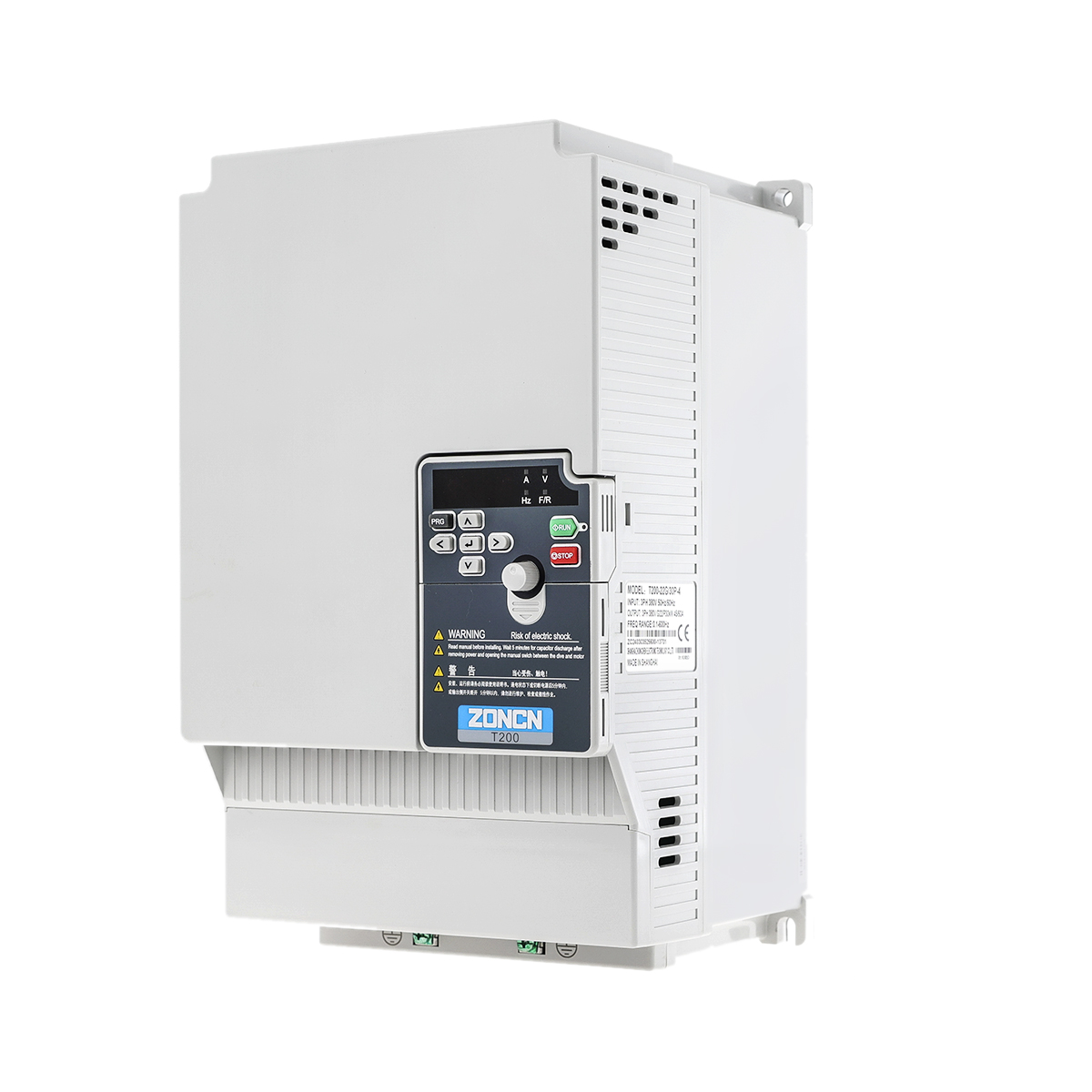
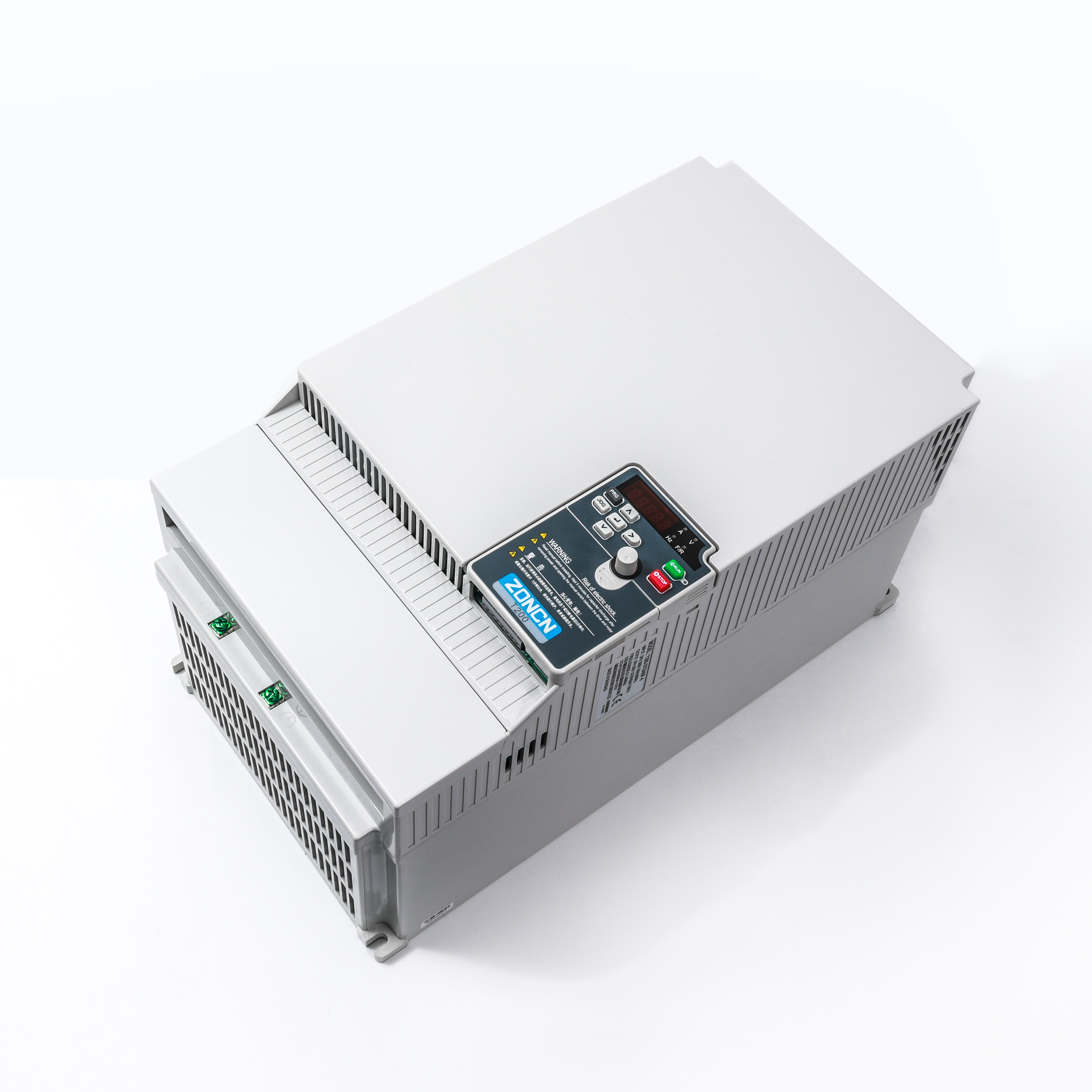
Display and operation panel | LED display | It displays the parameters. |
Key locking and | It can lock the keys partially or completely and define the function range of some keys so as to prevent mis-function. | |
function selection | ||
Protection mode | Motor short-circuit detection at power-on, input output phase loss protection, over-current protection, over-voltage protection, under voltage protection, overheat protection and overload protection. | |
Environment | Installation location | Indoor, avoid direct sunlight, dust, corrosive gas, combustible gas, oil fog, steam, drip or salt. |
Altitude | Lower than 1000 m(Lower the grades when using higher then 1000m) | |
Ambient temperature | -10°C ~40°C (Lower the grades if the ambient temperature is between 40°C and 50°C) | |
Humidity | Less than 95%RH, without condensing | |
Vibration | Less than 5.9m/s2(0.6g) | |
Storage temperature | -20℃~+60℃ | |
Running | Command source | Operation panel given, control terminal given, serial communication port given.It can be switched in various ways |
Frequency source | 10 frequency sources: digital given, analog voltage given, analog current given,pulse given,serial port given.It can be switched in various ways | |
Auxiliary frequency | Of the 10 auxiliary frequency sources. It can flexibly assist frequency fine-tuning and frequency synthesis | |
source | ||
Input terminal | 5 digital input terminals, one of which supports a high-speed pulse input of upto 100kHz; One analog input terminal supports O to 10V,voltage input or 4 to 20mA current input | |
Output terminal | 1 collector output terminal | |
1 relay output terminal | ||
1 analog output terminal to support 0~20mA current output or 0~10V voltage output | ||
Display and operation panel | LED show | Display parameters |
Key lock and function selection | Implement part or all of the keys lock, define the scope of part of the keys to prevent wrong operation | |
Protective function | Short-circuit detection, output phase deficiency protection, overcurrent protection, overvoltage protection, undervoltage protection, overheating protection, overload protection, etc. | |
Environment | Installation location | Indoor, free from direct sunlight, dust, corrosive gas, combustible gas, oil smoke, vapor, drip or salt. |
Altitude | Lower than 1000m | |
Ambient temperature | -10℃~+40℃(de-rated if the ambient temperature is between 40℃~50℃) | |
Humidity | Less than 95%RH,without condensing | |
Vibration | Less than 5.9m/s²(0.6g) | |
Storage temperature | -20℃~+60℃ | |
Model | Input Current (A) | Output Power(kW) | Output Current (A) | Motor (kW) |
Input voltage:1PHAC220V±15% | ||||
T200-0R4G-2 | 5.4 | 0.4 | 2.1 | 0.4 |
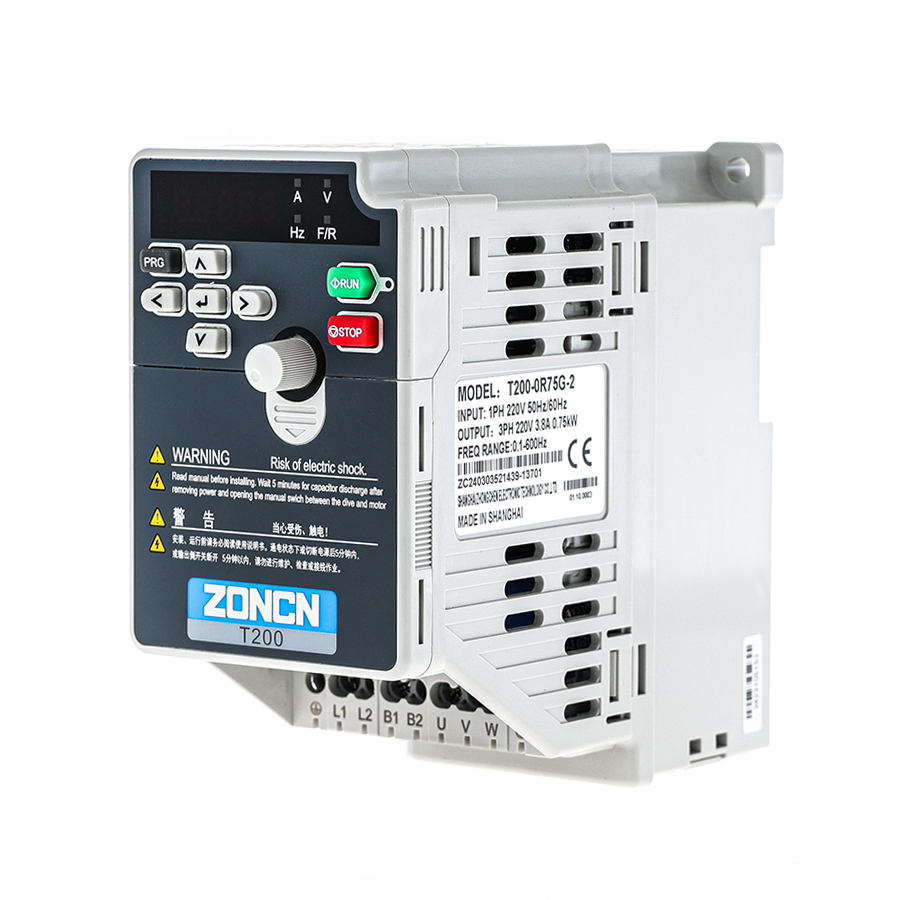
T200-0R75G-2 | 7.2 | 0.75 | 3.8 | 0.75 |
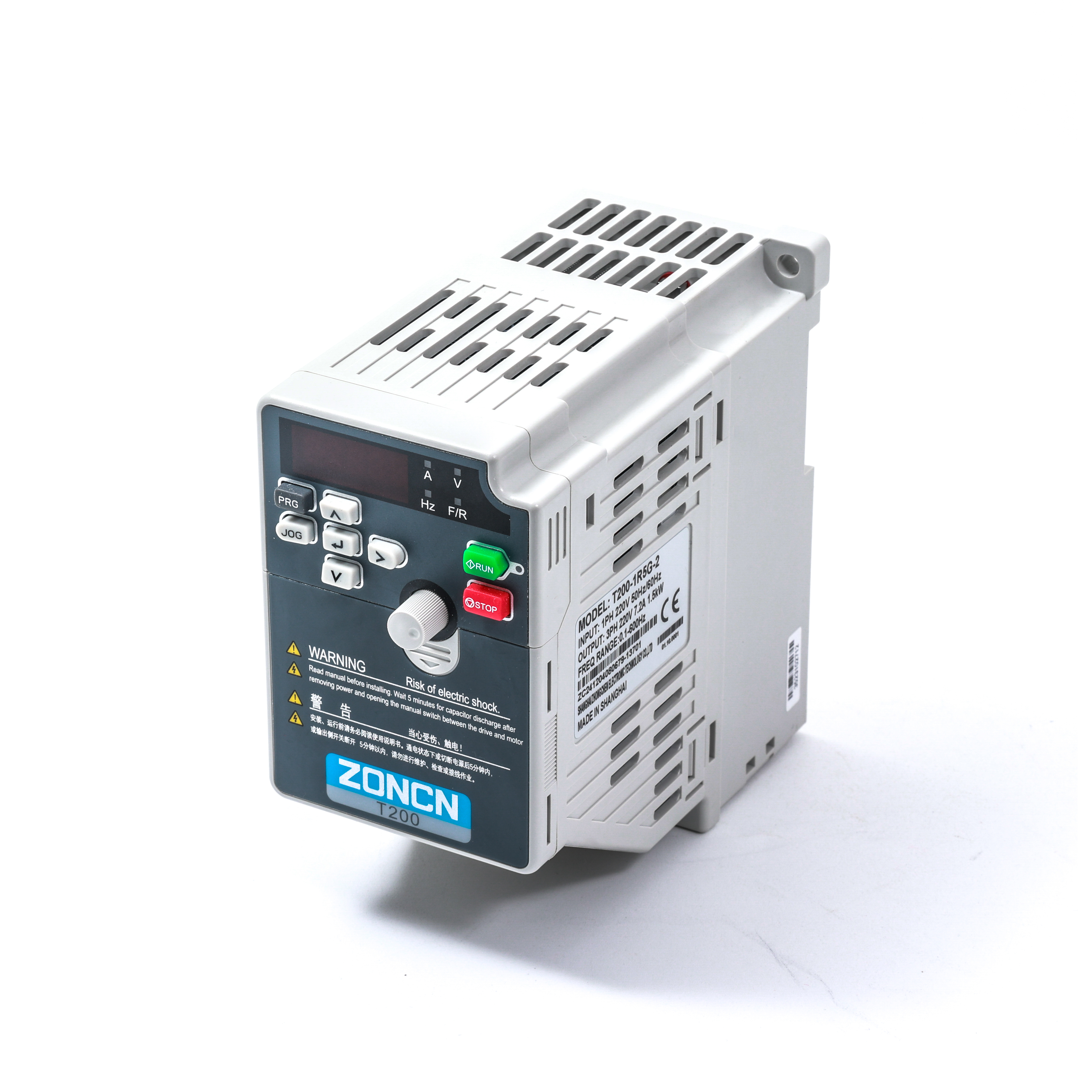
T200-1R5G-2 | 10 | 1.5 | 7.2 | 1.5 |
T200-2R2G-2 | 16 | 2.2 | 9 | 2.2 |
T200-3R7G-2 | 23 | 3.7 | 13 | 3.7 |
Input voltage:3PHAC380V±15% | ||||
T200-0R4G-4 | 3.4 | 0.4 | 1.5 | 0.4 |
T200-0R75G-4 | 3.8 | 0.75 | 2.1 | 0.75 |
T200-1R5G-4 | 5.0 | 1.5 | 3.87 | 1.5 |
T200-2R2G-4 | 5.8 | 2.2 | 5.1 | 2.2 |
T200-3R7G/5R5P-4 | 10/15.0 | 3.7/5.5 | 9.0/13 | 3.7/5.5 |
T200-5R5G/7R5P-4 | 15 | 5.5 | 13 | 5.5 |
T200-7R5G/11P-4 | 20/26 | 7,5/11 | 17/25 | 7,5/11 |
T200-11G/15P-4 | 26/35 | 11/15.0 | 25/32 | 11/15.0 |
T200-15G/18.5P-4 | 35/38 | 15/18.5 | 32/37 | 15/18.5 |
T200-18.5G/22P-4 | 38/46 | 18.5/22 | 37/45 | 18.5/22 |
T200-22G/30P-4 | 46/62 | 22/30 | 45/60 | 22/30 |
T200-30G/37P-4 | 62/76 | 30/37 | 60/75 | 30/37 |
T200-37G/45P-4 | 76/90 | 37/45 | 75/91 | 37/45 |
T200-45G/55P-4 | 92/113 | 45/55 | 91/112 | 45/55 |
T200-55G-4 | 113 | 55 | 112 | 55 |
Number | Expansion card external model | Function Description | Applicable Models |
1 | PG-T11-01 | ABZ-Differential Input PG Card-5V | T2000.4-55KW |
2 | PG-T11-02 | ABZ-OC&Push Pull Input PG Card-24V | |
3 | ET-T11-01 | 1 normally open/normally closed relay 2 DI,1 FIV,1 FOC | |
4 | ET-T11-02 | 1 high-speed pulse output 2 DI,1 FIV.1 FOC | |
5 | CM-T11-01 | Profibus DP communication card | |
6 | CM-T11-02 | EtherCAT communication card | |
7 | CM-T11-03 | CANopen | |
8 | CM-T11-04 | Modbus TCP communication card | |
9 | CM-T11-05 | Profinet communication card | |
Note:T200 support only 1 expansions cards. | |||
Basic wiring diagram
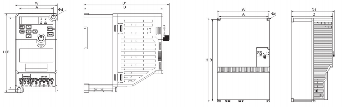
SIZE | Model | External dimensions | Installation dimensions | Installation method | ||||||
W | H | D | D1 | A | B | ①d | ||||
A | T200-0R4G-2 | 69 | 129 | 129 | 139.5 | 56 | 118 | 5.5 | Wall mounting | |
T200-0R75G-2 | ||||||||||
T200-1R5G-2 | ||||||||||
T200-0R4G-4-D | ||||||||||
T200-0R75G-4-D | ||||||||||
T200-1R5G-4-D | ||||||||||
T200-2R2G-4-D | ||||||||||
B | T200-0R4G-4 | 109 | 129 | 133 | 142 | 96 | 118 | 5.5 | ||
T200-0R75G-4 | ||||||||||
T200-1R5G-4 | ||||||||||
T200-2R2G-4 | ||||||||||
T200-3R7G/5R5P-4 | ||||||||||
T200-2R2G-2 | ||||||||||
C | T200-5R5G/7R5P-4 | 125 | 185 | 165 | 174 | 113 | 175 | 5.5 | ||
T200-7R5G/11P-4 | ||||||||||
D | T200-11G/15P-4 | 138 | 260 | 165 | 174 | 126 | 250 | 5.5 | ||
T200-15G/18.5P-4 | ||||||||||
E | T200-18.5G/22P-4 | 168 | 282 | 165 | 174 | 152 | 268 | 7 | ||
T200-22G/30P-4 | ||||||||||
F | T200-30G/37P-4 | 205 | 364 | 197 | 206 | 189 | 350 | 7 | ||
T200-37G/45P-4 | ||||||||||
G | T200-45G/55P-4 | 262 | 420 | 205.5 | 214.5 | 246 | 405 | 7 | ||
T200-55G-4 | ||||||||||