- CN
- EN


VINAC
MCCB with Residual Current Protection, MCCB, Molded Case Circuit Breaker, MCCB Circuit Breaker, Low Voltage MCCB, Industrial MCCB, Compact MCCB, 3P MCCB, Thermal Magnetic MCCB, Electronic MCCB, 16A MCCB, 32A MCCB, 63A MCCB, 100A MCCB, 200A MCCB, 400A MCCB, 630A MCCB, 800A MCCB, Overload Protection MCCB, Short Circuit Protection MCCB, Overcurrent Protection MCCB
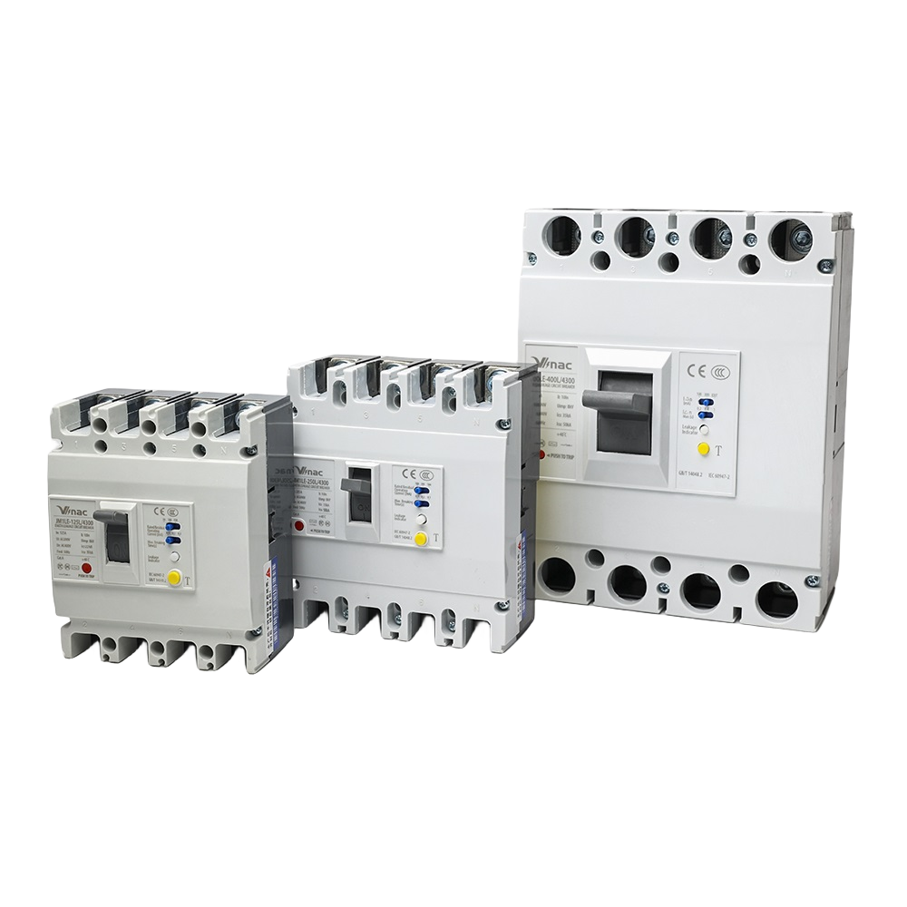
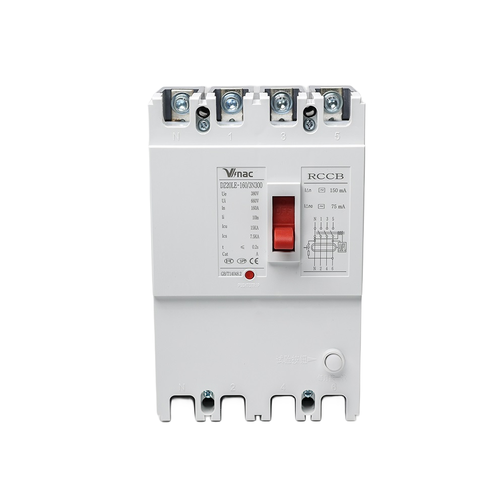
JM1L series residual current circuit breakers (hereinafter referred to as RCBOs) are mainly suitable for distribution networks with AC 50Hz, rated voltage AC400V, and insulation voltage up to 800V. They are used to provide indirect contact protection for people, prevent fire hazards caused by equipment insulation damage and ground fault currents, and can be used to distribute electrical energy and protect circuits and power equipment from overload and short circuits, It can also be used for infrequent switching of circuits and infrequent starting of motors. The working power supply of the conventional leakage protection module with RCBO is sampled as two phases. This series of RCBOs is 3 phase. If any phase is missing, the leakage protection module of the RCBO can still work normally. The rated residual operating current In and maximum disconnection time can be adjusted on-site according to actual conditions: When the phase voltage drops to 50V, the leakage protection module can still operate normally and has a leakage alarm output function.
The product meets the standards of IEC60947 and GB14048. 2
2. Model and meaning

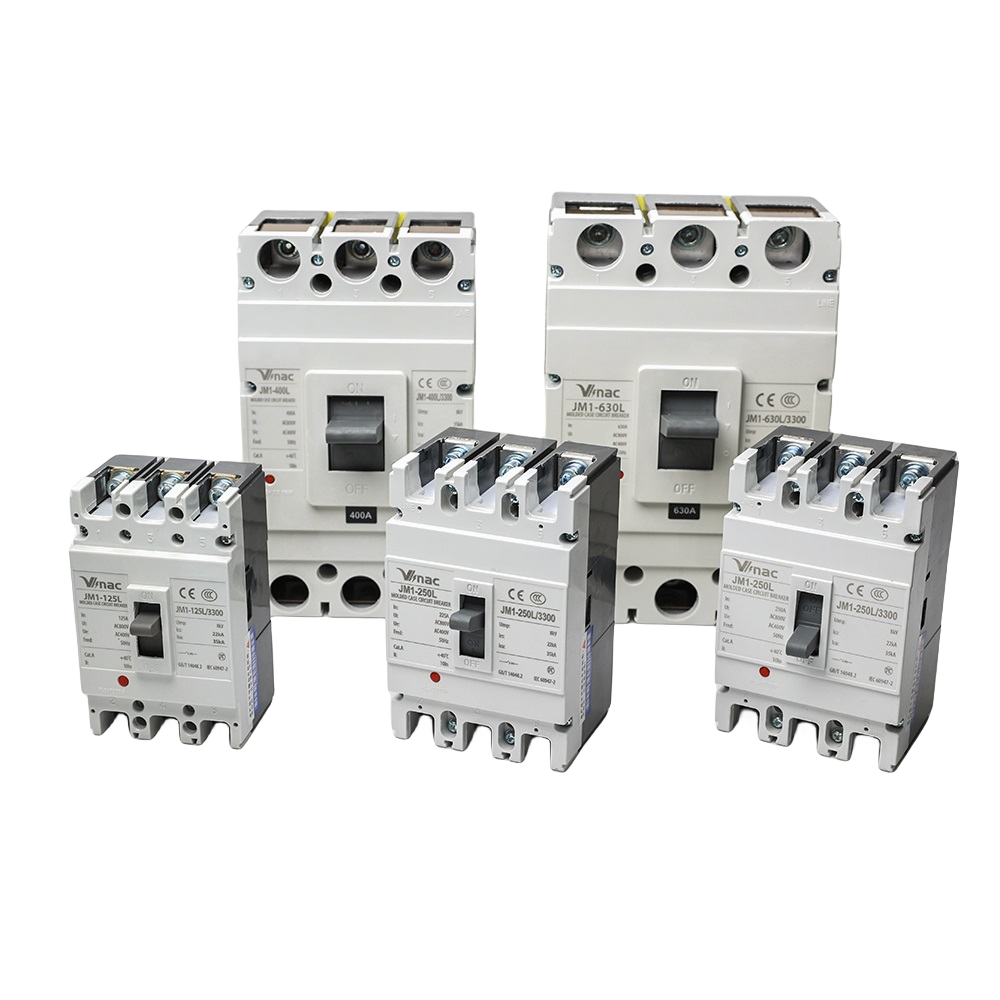
Model | Rated Current | Breaking Capacity | Poles |
JM1L-100 JM1L-125 | 16-125A | 35kA | 3P 3P+N 4P |
JM1L-225 | 100-225A | 50kA | 3P 3P+N 4P |
JM1L-400 | 250-400A | 50kA | 3P 3P+N 4P |
JM1L-630 | 400-630A | 50kA | 3P 3P+N 4P |
JM1L-800 | 800A | 50kA | 3P 3P+N 4P |
Table 1 Separation Method and Attachment Code

Normal usage conditions:
a)The upper limit of the ambient air temperature shall not exceed+40℃, the lower limit shall not be lower than -5℃ , and the average value within 24 hours shall not exceed+35℃ .
Note: Circuit breakers used under conditions where the ambient air temperature is above+40℃ or below -5℃ should be negotiated with the manufacturer.
b)The height of the poster at the installation site shall not exceed 2000m;
c)The relative humidity of the atmosphere does not exceed 50%at the highest ambient temperature of+40 ℃;At lower temperatures, there can be higher relative humidity(e. g. 90%at 20℃), taking into account the condensation on the surface of the product caused by temperature changes
Normal installation conditions:
a)Installation conditions: Generally, it should be installed vertically or horizontally;
b)Installation category: Circuit breaker main circuit Class II, control circuit and auxiliary circuit Class ;
c)Pollution level:Level 3;
d)External magnetic field:The external magnetic field near the installation site shall not exceed 5 times the geomagnetic field in any direction.

Model | Number of poles | External dimensions(mm) | Installation dimensions(mm) | |||||
L1 | L2 | L3 | L4 | a | b | Φ d | ||
JM1L-100S | 3 | 92max | 150max | 94max | 75max | 30 | 129 | 4*φ4. 5 |
4 | 122max | 150max | 94max | 75max | 60 | 129 | 6*φ4. 5 | |
JM1L-100H | 3 | 92max | 150max | 110max | 92max | 30 | 129 | 4*φ4. 5 |
4 | 122max | 150max | 110max | 92max | 60 | 129 | 6*φ4. 5 | |
JM1L-225S | 3 | 107max | 165max | 94max | 72max | 35 | 126 | 4*φ4. 5 |
4 | 142max | 165max | 94max | 72max | 70 | 126 | 6*φ4. 5 | |
JM1L-225H | 3 | 107max | 165max | 110max | 90max | 35 | 126 | 4*44. 5 |
4 | 142max | 165max | 110max | 90max | 70 | 126 | 6*φ4. 5 | |
JM1L-400S, H | 3 | 148max | 257max | 146max | 100max | 47 | 194 | 4*φ7 |
4 | 197max | 257max | 146max | 100max | 95 | 194 | 6*φ7 | |
JM1L-630. 800S, H | 3 | 210max | 280max | 146max | 103max | 70 | 243 | 4*φ7 |
4 | 280max | 280max | 146max | 103max | 70 | 243 | 6*φ7 | |

Model | External dimensions | Installation dimensions(mm) | |||||||||
L1 | L2 | L3 | H1 | H2 | a1 | b1 | Φ D | Φ d | |||
3P | 4P | 3P | 4P | ||||||||
JM1L-100 | 164 | 132 | 35 | 53 | 93 | 72 | 102 | 90 | 132 | 22 | 5. 5 |
JM1L-225 | 173 | 144 | 35 | 55 | 100 | 87 | 122 | 93 | 144 | 24 | 5. 5 |
JM1L-400 | 267 | 144 | 37 | 70 | 120 | 87 | 122 | 93 | 225 | 26 | 6. 5 |
JM1L-630. 800 | 295 | 210 | 37 | 75 | 125 | 87 | 122 | 93 | 243 | 48 | 7. 0 |
Appearance and installation dimensions of wiring after inserting the board

Model Unit in mm | W | L | A | H1 | G | G1 | a | b | Φ d | ||
3P | 4P | 3P | 4P | ||||||||
JM1L-100 | 94 | 125 | 170 | 38 | 50 | 33 | 38 | 60 | 90 | 56 | 6. 5 |
JM1L-225 | 110 | 145 | 188 | 48 | 50 | 33 | 40 | 70 | 105 | 54 | 7 |
JM1L-400 | 144 | 188 | 280 | 50 | 60 | 37 | 48 | 88 | 132 | 143 | 9 |
JM1L-630. 800 | 212 | 282 | 298 | 57 | 100 | 43 | 129 | 140 | 210 | 143 | 9 |

Model | JM1L-100 | JM1L-225 | JM1L-400 | JM1L-800 |
Installation dimensions(H) | 49 | 55 | 74 | 66 |